⚙️ Mechanical Engineering Resources:
We have put a dozen guides for mechanical engineering students and early professionals on our website
50 Hardware Startups who have raised less than $50 million (perfect internship targets)
How to handle The Behavioral Interview
What it take to be The 10X Intern
💼 Jobs & Internships
Internship season is in full swing! The race is on!
Freshmen - Check out our 4-Year Plan for how to get internships at startups!
Sophomores - Apply To These Positions
Amphenol Mechanical Engineering Intern - Summer 2025
RTX Mechanical Engineering Intern
Sierra Space Mechanical Engineering Intern - Summer 2025
Juniors - Full Send Longshots!
Rivian Engineering Intern - Prototype, Mechanical Chassis Engineering
The Boring Company Mechanical Engineering Intern - Winter/Summer 2025
Zoox Mechanical Engineering Intern/Co-op
Seniors & Graduates - It’s Go (Full) Time!
Super Tough:
Nike Product Development Engineer I - Design
Crusoe Mechanical Engineer
Fleet Robotics Inc. Mechanical Engineer - Underwater Robotics
More Reasonable:
Markforged Mechanical Engineer II
Textron Mechanical Engineer
K2 Space Satellite Mechanical Engineer
Not seeing what you are looking for? Check out our Job Board for more MechE positions!
👶 Meme Of The Week
🙋♂️ FEA Field Guide
As I began my journey in mechanical engineering, I remember vaguely knowing that FEA was something that I needed to know how to do, but not knowing where to start (iirc the list was FEA, Arduino, Matlab and LabView - I guess those are the skills I thought of as related to engineering when I was 18). It’s a daunting challenge to begin on your own - what software to use? What material considerations do I need to take into account? What type of analysis fits my load cases? What’s a contact set? And how is a fixture different from that? Mesh size? These are a few of the basic questions I’ll try to address below:
FEA in pretty much any software has a general flow to it:
(Hand-calcs) —> Simulation Type —> Geometry and Material —> Fixturing & Contact Sets —> Loading —> Meshing —> Results
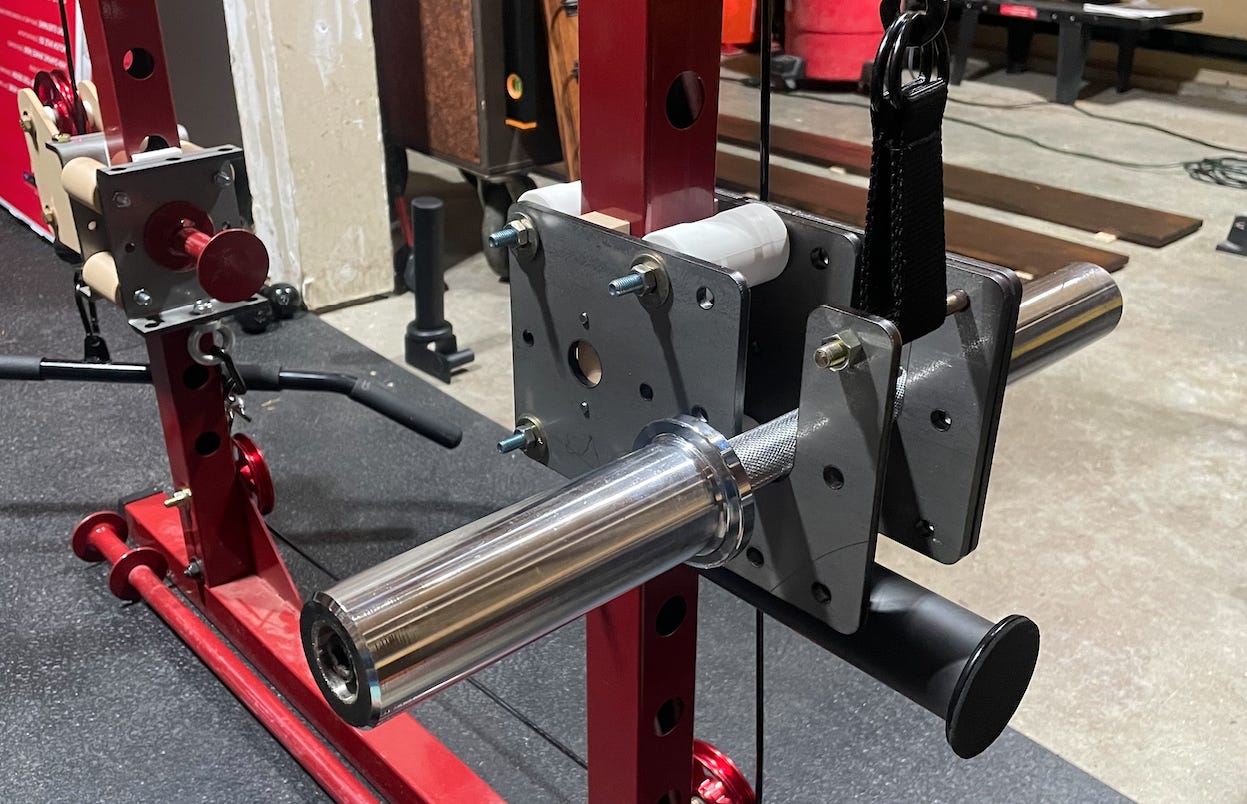
We had an avid user submit a design they had for some at-home gym equipment made out of sheet metal! This is one of our favorite ways to come up with a personal project: need something, find it on Amazon, decide it’s stupidly expensive ($189 in this case), then design and fabricate it! Their project is what we will be doing practice analysis on for this article (read till the end to find out how much it cost).
[ 0. Hand Calcs ]
Generally speaking, hand calcs are invaluable. They are a great way to provide a quick temperature check prior to running simulation (which can take time to setup, mesh and run). That is what ~50% of our newsletters have focused on historically: How to simplify real world use cases down to a basic load case on a simple enough structure that we can estimate the stress or deflection in (coincidentally those are the most common interview questions). It’s an invaluable skill that will honestly change how you view the world over time. However, when working on something where every gram of mass costs $$$ or where “probably fine” just isn’t good enough, you’ll probably have to bring out the big guns (FEA).
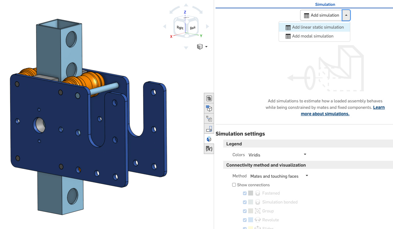
1. Simulation Type Selection
Picking the right type of simulation is like picking the right lens for a camera—each type brings a different focus to the problem. Your software will typically have options like static structural, modal, thermal, nonlinear, or dynamic simulations, among others. The choice boils down to what you’re analyzing and how it behaves under loads. Here’s a quick breakdown:
Static Structural: TBH this is the one you’re going to use 90% of the time unless you specialize in FEA. Static structural is for cases where loads can be approximated as constant with respect to time. This is the bread and butter for most mechanical designs, and a crucial part of most complete design processes in industry. For reference, imagine a spring finger on a plastic injection molded piece you’re designing. Static structural analysis can help you figure out how much deformation it can sustain before yielding, where it’ll yield, and maybe even calculate insertion force.
Modal Analysis: As the name implies, this type of analysis is mainly for finding the shape of the primary, secondary and tertiary modes of the component as well as the natural frequency. This is very popular for aerospace and automotive particularly, as large components under a steady vibration at the wrong frequency can undergo tremendous force (and deflect wildly).
Thermal Analysis: This is pretty self explanatory. If you need to assess how temperature affects materials—useful for electronics or high-heat applications—this one’s for you.
Dynamic Analysis: This is for situations where loads or constraints change over time, like drop or shock impacts. As you might imagine, this type of analysis (and testing) is very popular in the consumer electronics industry.
2. Geometry Import & Material Assignment
Most software allows you to import a CAD model, but it’s essential to review your model before jumping in. Simplify wherever possible. Remove unnecessary details like threads, embosses, or bolt heads that don’t influence the structural integrity (every tiny feature adds to computation time). Intersecting geometry or broken surfaces may also result in a non-convergent model.
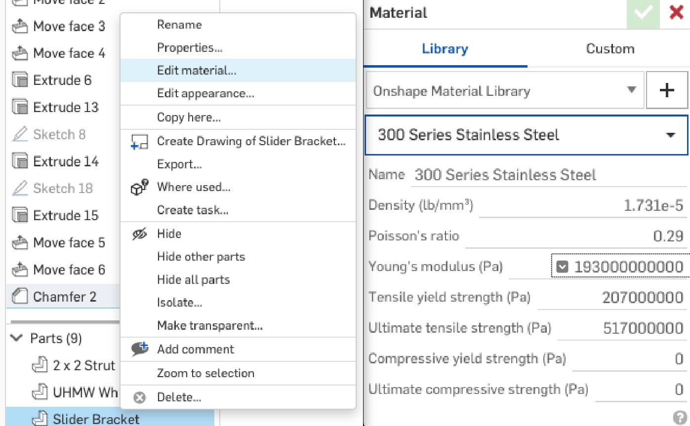
Many simulation softwares have an in-built material bank. Personally, I tend to use it and cross reference a few critical parameters with Google but leave the rest alone: Young’s modulus, Poisson’s ratio, density and yield strength. CTE if it’s a thermal simulation. Many larger companies will have an in-house materials database finely tuned with real world test data relevant to them. Also of note is that sometimes properties like CTE are non-linear across temperature, so make sure to input values at the correct temperature or use a table of data containing parameters across temperature (though you’ll still have to specify temperature later if it’s relevant).
The golden rule (of FEA but also data and maybe life(?) in general): garbage in, garbage out — select the material that aligns with the real-world scenario you’re trying to simulate. If some properties are estimates, that’s okay, but make sure to call it out as an assumption and potential source of inaccuracy when presenting the results.
3. Fixturing & Contact Sets
Fixtures define the constraints—essentially, you’re telling the model what parts of it are held still or locked down, so it doesn’t start spinning off into the ether when a load is applied. In FEA lingo, this is called a boundary condition.
Fixturing can be as simple as saying “this face is fixed” (as in the case of a Command hook adhered to a wall) or more complex, where certain areas allow movement only in specific directions (a pin in a slot). I’m no FEA guru, but typically I fix a face or body as the starting point of my analysis, then go through how everything else interacts with it. For this analysis, I’ve chosen to fix the central strut.
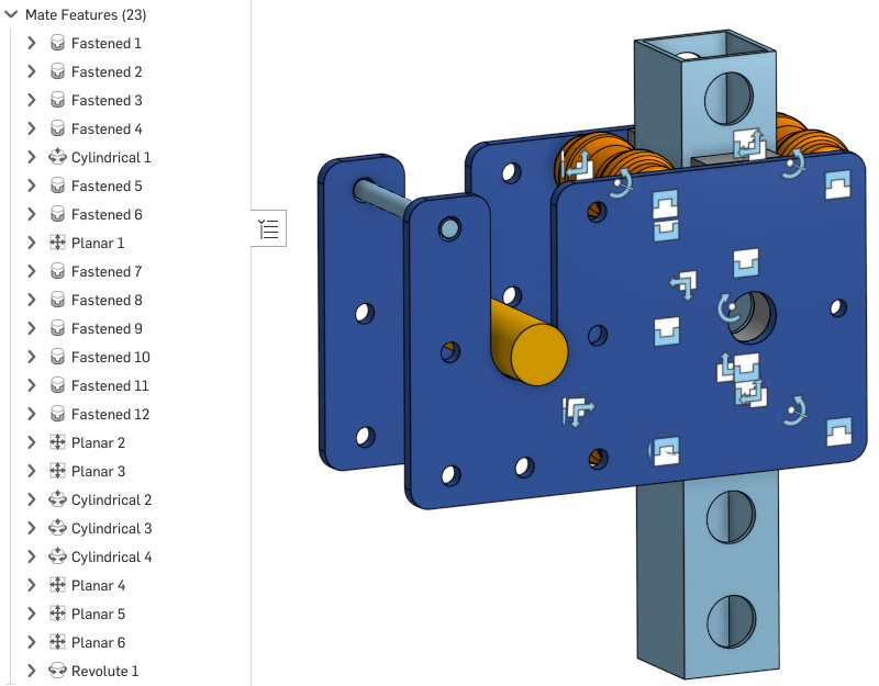
When working with assemblies, contact sets tell the software how parts interact—whether they’re bonded together, sliding against each other, or can separate under load. Different types of contacts, such as bonded, sliding, and frictional, simulate real-world interfaces between parts. Note that there are many different names and types for these contacts depending on the simulation software you are using. Onshape, for example, appears to use “mates” to dictate part interactions.
4. Load Cases
Load cases are where you define what forces, pressures, or thermal conditions your part will experience. This might be as simple as a static force applied to one face, or it could involve a stepped loading condition or enforced displacement.
Careful definition of load cases is essential to getting useful results. Luckily, it’s also relatively self explanatory most of the time. For example, here I’ll apply a load approximating weights pulling down on the weight bar, and someone lifting from the cable attachment bar. For this simulation, that means 200 lbf in the -Z and +Z directions on the appropriate bodies.
5. Meshing
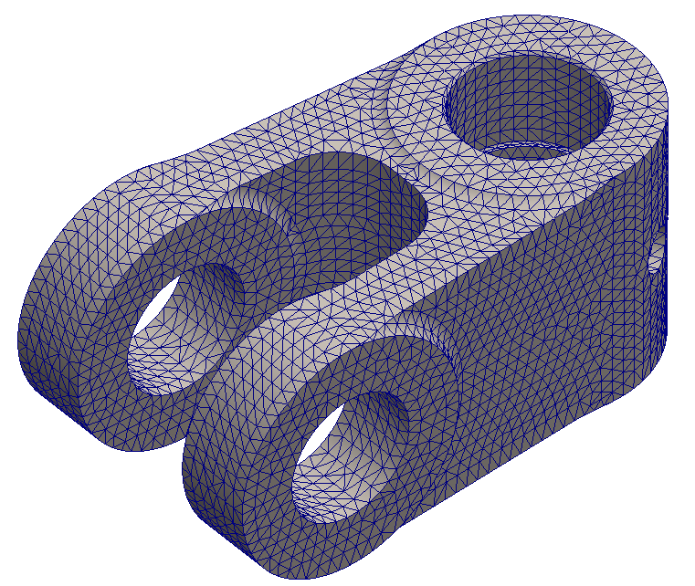
In short, meshing divides your model into small elements that the software can do calculations on. I won’t get into the minutia of it here, but the basics of how FEA works (i.e. the finite element method - FEM), is by breaking up part geometry into thousands of tiny triangles (depending on the mesh type you’ve chosen) and modeling the interactions between each triangle. As each triangle only experiences a slightly different stress/deformation relative to the triangle next to it, we are able to approximate the entire model. This is, of course why ruptures and cracks are very difficult to model, though there are some cool meshing features coming out that can help with that these days (basically remeshes everytime a deformation threshold is reached).
In principle, the finer the mesh, the higher the accuracy, but this also means longer computational times. Also, garbage in, garbage out. A fine mesh will not make your model more accurate if it’s setup improperly. Plus, there is absolutely a point at which further meshing functionally does nothing to improve your model. Mesh where needed. Resist the temptation to apply a super fine mesh everywhere.
First pass, I usually apply an adaptive mesh (basically “auto-mesh” based on the software’s built-in capabilities). I then inspect and apply a finer mesh to any faces of particular concern (expected stress concentrations) or small features that haven’t been scrubbed out in the initial geometry preparation. By doing this, I am attempting to ensure that areas of high gradient (high changes in stress or deformation per unit length) are well described by the mesh to help with convergence.
General rule of thumb is to have at least two elements across any surface, and more elements in areas of high stress gradients. Small holes can add a shocking amount of computational complexity (mesh has to weave around and into the hole). Fillets might seem like a great thing to take out, and they can be, but not in areas of high stress. Corners or point contacts can easily create what is called a “singularity.” Basically, it is a region where load is divided by zero (or some very small number) and stress is calculated as infinite. This is frequently the source of divergence when a simulation is taking longer than you think it should to run.
In Onshape, there basically are no meshes! Fortunately, I found Onshape’s simulation capabilities to be very generous in terms of convergence. Convergence means that the software thinks it has found a passable solution. This cannot occur if parts are flying away (if unconstrained properly) or if the stress far exceeds the ultimate strength of the material. Onshape has a cool feature where it displays iteration results even while it works towards a convergent solution, so you can literally watch the results refine as the model moves toward ultimate covergance. The upside, is that you will almost always be able to get a model that has results relatively easy with a proper setup. On the downside, it becomes much more difficult to refine the mesh or remove point discontinuities for further tuning/accuracy. Luckily, if that further accuracy is required, you can still import the mesh from elsewhere as desired and run the analysis like normal.
6. Results
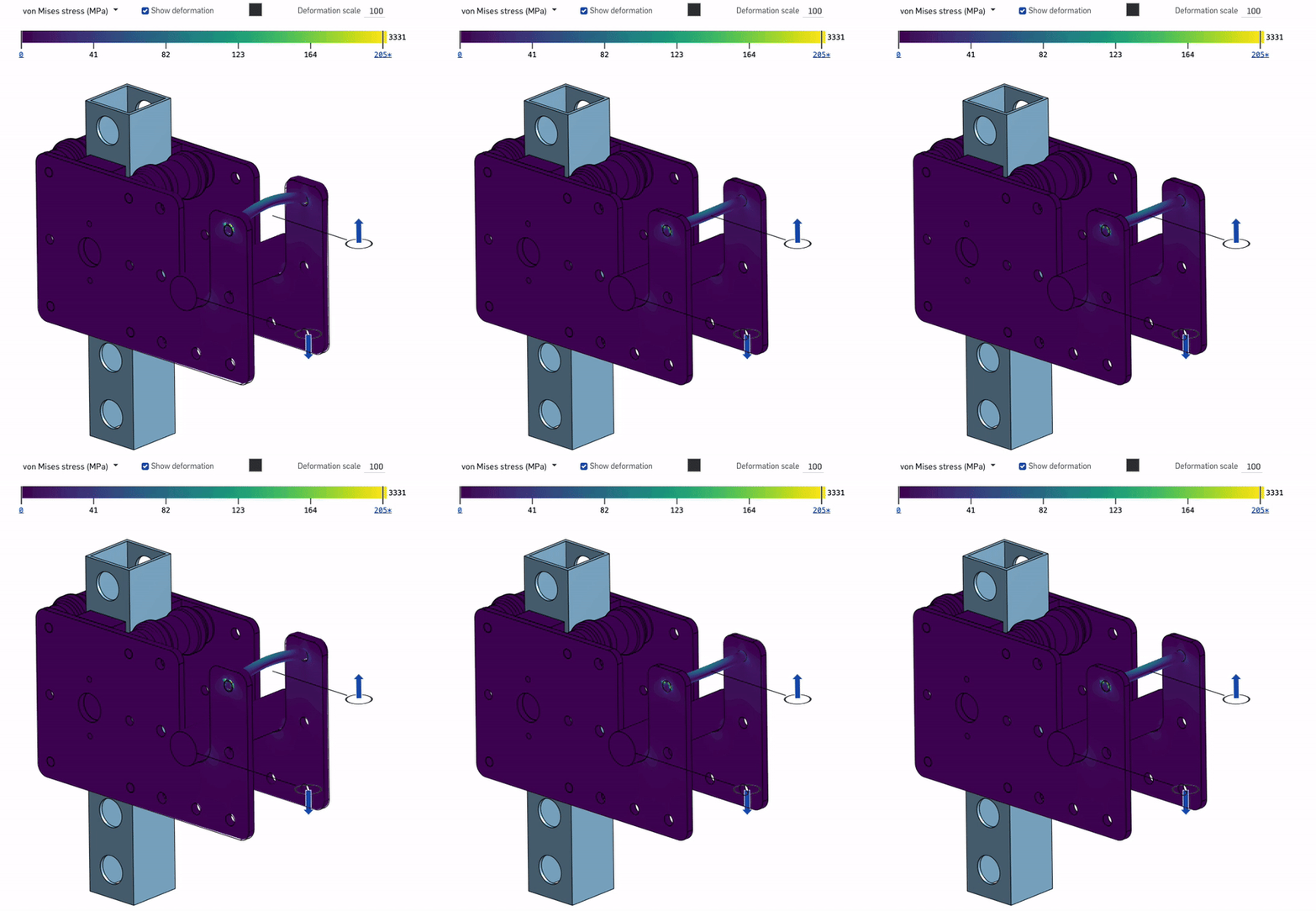
Results time! Looking at the .gif, I don’t see much in the way of obvious issues (note that deformation is scaled 100X). The yield strength of 304 stainless steel is ~205 MPa, (why I set the far right indicator of the legend at 205). The fact that the max stress of the model is 3331 MPa means that there is definitely a singularity. Looking closely, it seems that the plates experience almost no stress, though the cable bolt is a bit of a hotspot (though well below yield). It does however present itself as a weak point, especially since it is currently in double shear (only very low clamping force can realistically be achieved in this part assembly). For that reason I would recommend adding in a spacer (to enable bolt clamping) and potentially a thicker bolt. The plates can be pocketed or thinned substantially as they are extremely overbuilt for this scenario. Then again, gym equipment can experience a lot of unexpected forces (dropping heavy weights) so the downside to overbuilding the plate isn’t really a downside at all.
Zooming in on the end of the bolt, we see some odd streaks of very high stress. When encountering just a couple elements showing shockingly high stress, they can often be ignored. Those stresses just aren’t real, but rather vestigial artifact of the mathematical model used to run the simulation. They can sometimes be removed by going back and looking at how the part was constrained in the first place and may lead to further improvements in the accuracy of the model. Here, it is likely due to Hertzian contact (single point rounded contact surface) causing stress singularity. Shear or deformation of the cable bolt is likely the dominant failure mode for this system, however these stresses actually appear closer to the ends of the bolt rather than the interior edge of the plate (where shear would occur). As such, they can be ignored for the moment (or further refinement of the contact set could also probably solve the issue).
Et voila! The final result speaks for itself! I am told it works like a charm! Total cost of parts was $50-$100 depending on who’s fabbing it and how quickly it’s needed. Please note that this guide is only intended as a launching point for your simulation efforts. Hope you learned something!
***This newsletter was sponsored by Onshape.


